# Use Cases
# Case 1: MAC Address Management
The default MAC address of SwarmLink is FDFD0001, which can be customized changed for the purpose of networking.
Hardware:SwarmLink Gateway、SwarmLink Node、PC.
Software:EasySwarm2.0.
Note: You can only modify one node at a time, multiple nodes, please modify them separately.
# Modify the MAC address:
# 1. Open the gateway serial port
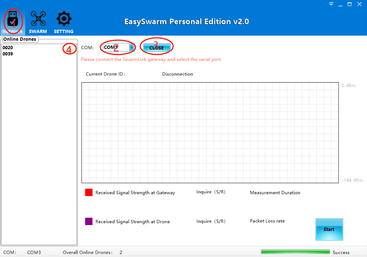
- Click on the "NETWORK" tab
- Select the serial port number of the gateway connection
- Click "Open" and "Success" is displayed in the lower right corner, indicating that the gateway has successfully accessed. At this point, the factory node can also be powered on.
- Click to refresh the list on the left. If the 0001 node appears, skip step 2.
# 2. Add 0001 node to the gateway (you can skip this step if you have added)
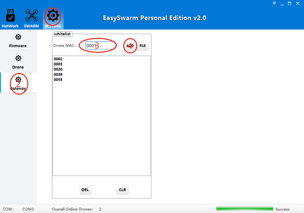
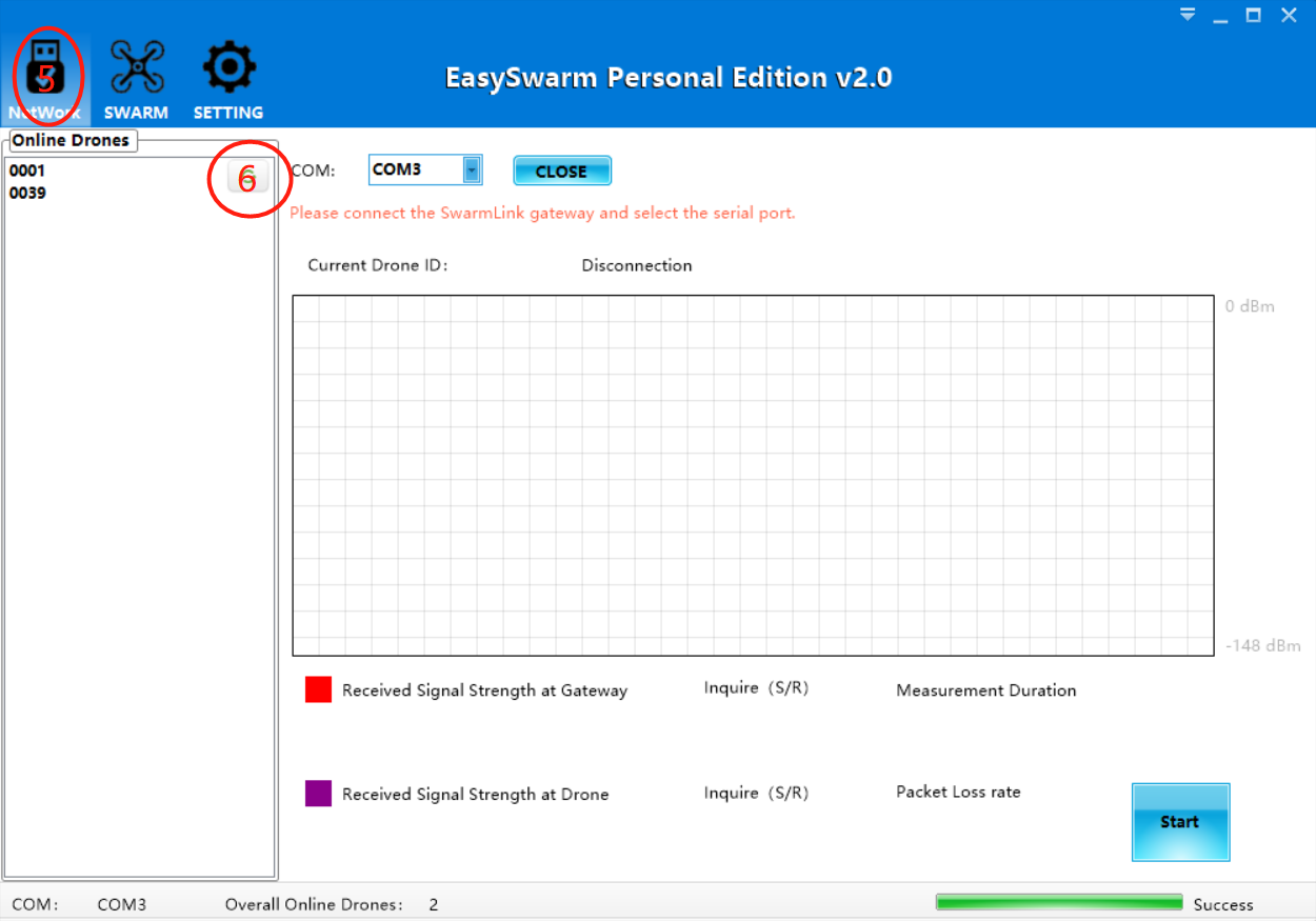 1. Switch to the "SETTING" tab 2. Click on "Gateway" 3. Enter the node MAC address: 0001, 4. Click "ADD". If you see the 0001 node in the white list below, the addition is successful. At this point, the factory node needs to be powered off and restarted. 5. Click on the "NETWORK" tab 6. Click Refresh to see if online node 0001 appears. If successful, go to step 3.
# 3. Modify the drone MAC address
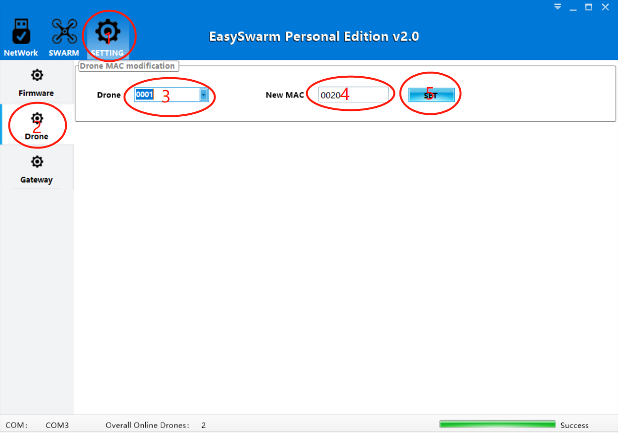 1. Click on the "SETTING" tab 2. Click on "Drone" 3. Pull down and select the "0001" node 4. Fill in the new 4-digit MAC address 5. Click on "SET" and the prompt "Success" will pop up. Power off and restart the factory node, then refresh the online node list to view the modification. Note: If the new MAC address is not in the gateway whitelist, repeat the Add Gateway Whitelist operation in step 2 and refresh again.
# Case 2: Single drone manual control
Hardware:Phenix Pro DevKit,RobSense RST330 research drone、SwarmLink gateway、SwarmLink node、PC
Software:EasySwarm2.0
Note: Before the drone is controlled by a single unit, you need to perform networking operations. Repeat steps 1 and 2 in Case 1 to complete the node addition. Once the drone node appears in the online list, you can proceed.
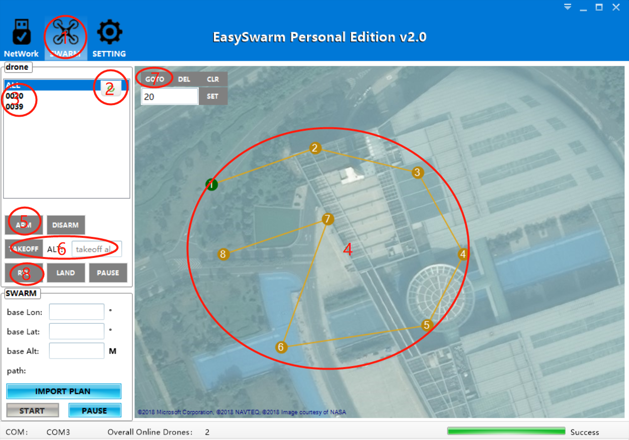
- Switch to the "SWARM" tab
- Click the refresh button
- The drone node appears in the list, left click to select
- In the map on the right, drag the map area with the left button, zoom in and out on the map, and right click on the map to plan the flight point. When finished, click the flight point No. 1.
- Place the drone near the flight point No. 1, click "ARM", wait for the drone to unlock.
- Set the takeoff height (m), click "TAKEOFF", wait for the drone to take off to the specified height.
- Click on "GOTO" and the drone will fly to the currently selected flight point.
- After completing the flight, click on "RTL" and the drone will return to the takeoff location and land automatically.
# Case 3: Automatically Swarming
Hardware:RobSense RST330 research drone,RobSense Phenix Pro DevKit,SwarmLink Gateway,SwarmLink Node,PC(windows).
Software:EasySwarm2.0
Note: Before swarm flight, you need to perform swarmLink networking and single-machine manual take-off and landing control test. For details, see Case 1 and Case 2.
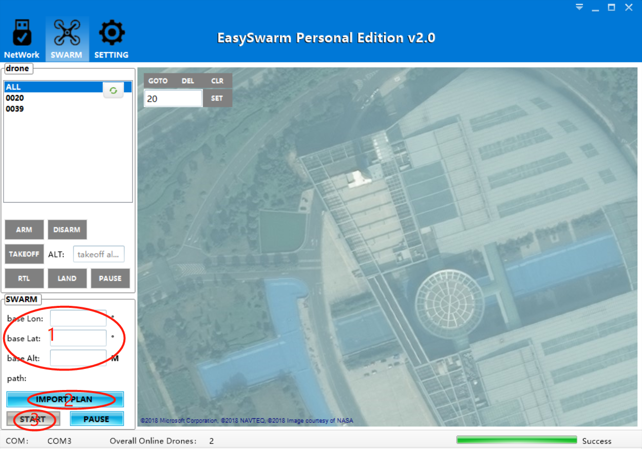
- Fill in the longitude, latitude, and altitude of the base point. The longitude and latitude need to be accurate to 6 digits after the decimal point, and the height is an integer greater than or equal to 0.
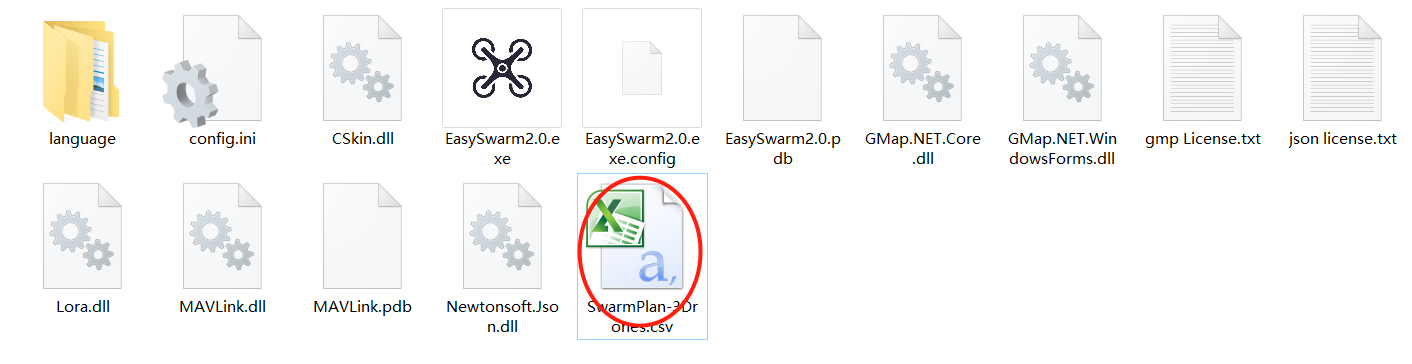
- Import flight plan file, the format is csv, can be opened with execl, there is "SwarmPlan-3Drones.csv" under the software root directory, which can be used as a test file to directly import flight. You can also write your own flight files according to the flight plan file format specification.
- Separate the drones on the ground, pay attention to the order of the drones (for example, the order of the demo files is from north to south, in the order of 1, 2, 3), click the "START" button. The drone will automatically execute the flight plan file at set intervals.
- In the process of swarm flight, if there is an accident, please click the "PAUSE" button of the formation function for the first time, then return or land according to the actual situation, and do not support direct return.
Note: The drone's ARM, TAKEOFF, GOTO, RTL and other operations can be completed in the flight plan file.
# Flight plan file preparation instructions:
Demo flight plan files are stored in the software directory. The following are flight file format specifications:
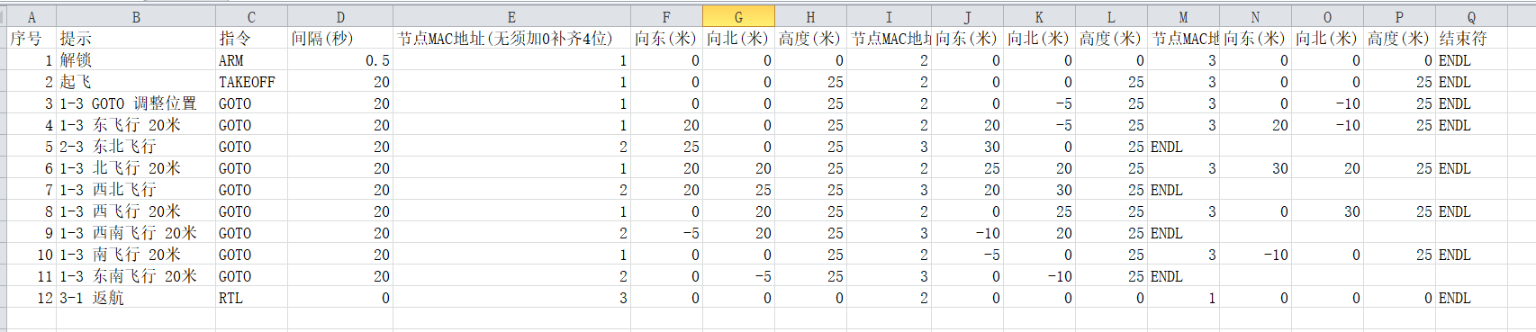
Column A - Serial number: starting from 1 and filling in ascending order.
Column B - Tip: Plain text content, only used to prompt the instruction of the line, improve readability.
Column C - Instruction: Includes ARM, TAKEOFF, GOTO, RTL. Only one flight instruction is allowed in a row.
Column D - Interval (seconds): After the execution of the command is completed, wait for N seconds and execute the next line. If the flight distance is long, it is recommended to increase the time interval.
Column E - Node MAC address (no need to add 0 to fill 4 digits): Fill in the MAC address of the drone node that needs to be in formation flight.
Column F- east (meter): If it is a GOTO command, it represents the offset of the flight point relative to the base point, with a positive integer to the east and a negative integer to the west.
Column G - north(meter):: If it is a GOTO command, it represents the north-south offset of the flight point relative to the base point, with a positive integer to the north and a negative integer to the south.
Column H-height (meter): If it is a TAKEOFF command, it represents the takeoff altitude of the drone; if it is a GOTO command, it represents the up and down offset of the flight point relative to the base point, up to a positive integer, down to Negative integer.
Column Q- terminator: Each line must be filled with an ENDL at the end, indicating the end of the line instruction.
← Quick Connections FAQ →